Predefined and custom programmes for all needs. The machine process is developed by our Automation department in compliance with current regulations/standards and the type of product being sterilised or depyrogenated. The DHS-series dry heat sterilisers have been designed to be ISO 14664-1-compliant (Class 100 according to US Federal Standard 209 E) up to a temperature of 300°C. Class 100 is guaranteed throughout the entire cycle (heating, sterilisation/depyrogenation and cooling phases). LAST Technology verifies and guarantees these performances during the machine’s FAT, by sampling the particle content inside the oven throughout the cycle (especially during the cooling phase which is the most critical due to the expansion and retraction of the frames and filters). The system also ensures optimum heat distribution throughout all the sterilisation/depyrogenation phases (temperature deviation of less than ± 2°C).
DHS
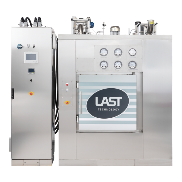
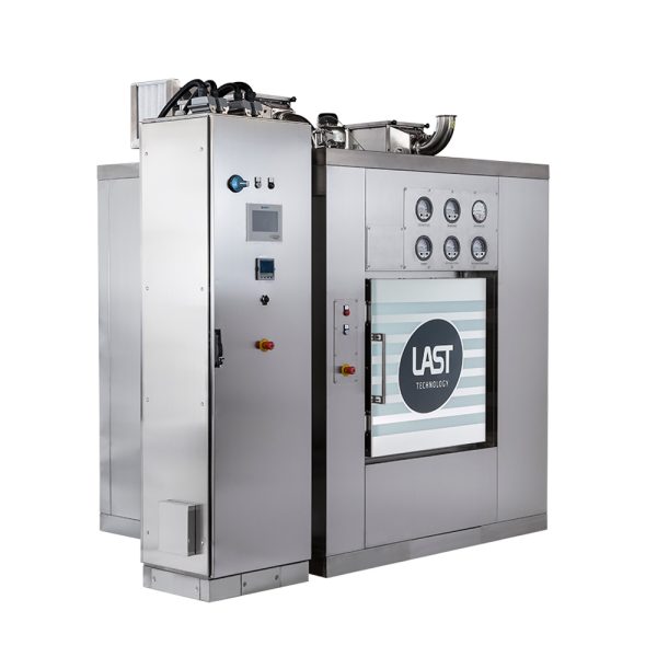
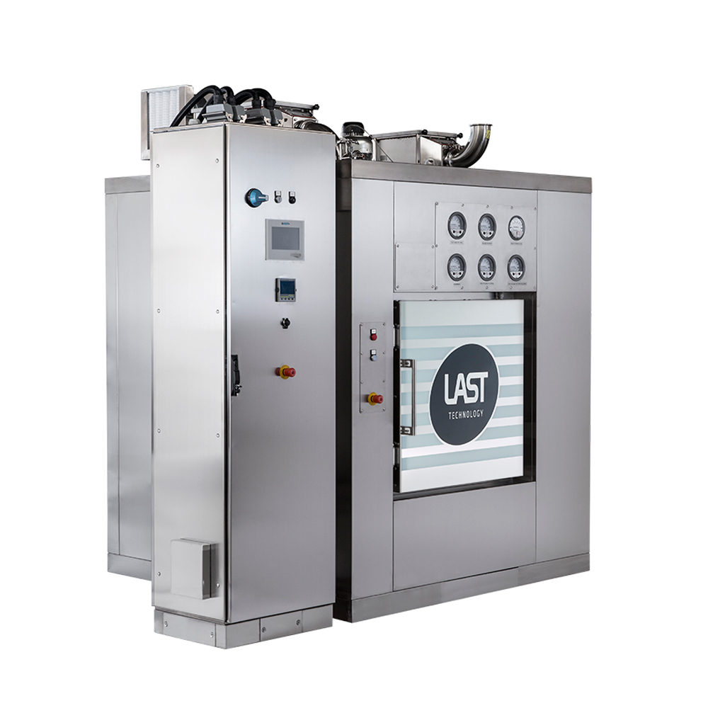
cGMP DRY HEAT STERILISER/ DEPYROGENATOR


DHS
cGMP DRY HEAT STERILISER/ DEPYROGENATOR
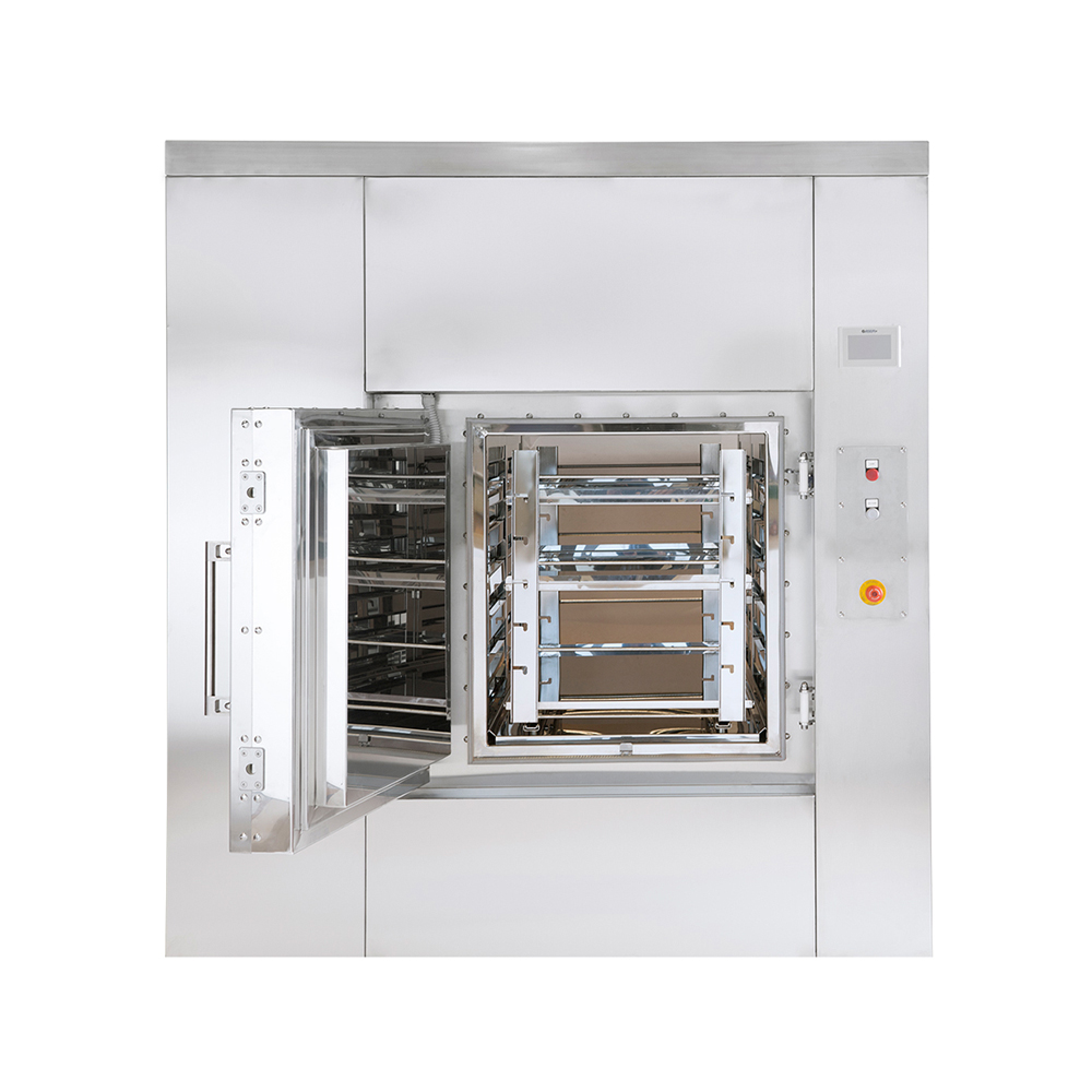
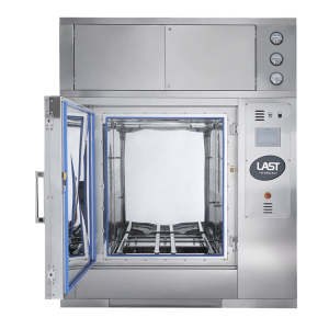
The DHS dry heat sterilisers have been designed to sterilise and depyrogenate empty Class 100 (ISO 5) glass containers, such as bottles, vials and stainless steel parts, using hot air. By retaining a temperature of 150-300°C for a controlled period of time, the microorganisms are inactivated and destroyed.

SOLIDS

AIR

150°C – 300°C
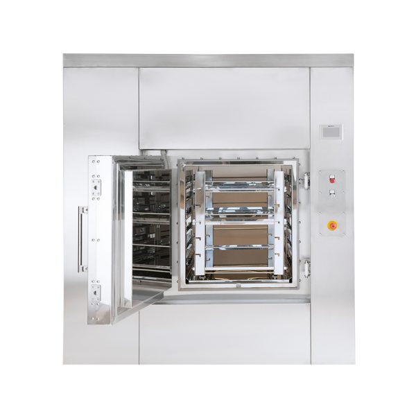
- Rectangular cross-section sterilisation/depyrogenation chamber and hatches (doors).
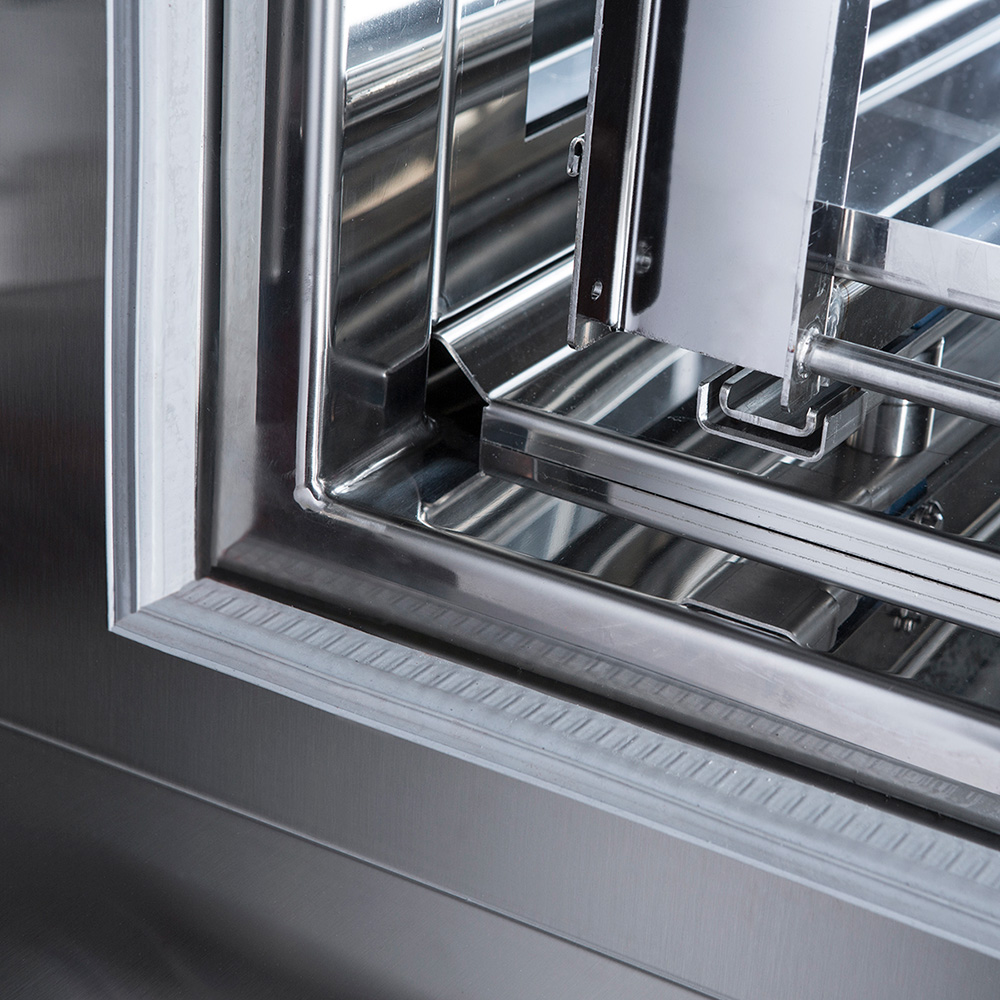
- The chamber is composed of one fully welded vessel with rounded corners to ensure excellent hygiene and facilitate the cleaning of inner surfaces.
- The chamber/base is fitted with a jacket for a quick and uniform load heating/cooling.
- Heat-resistant mechanical construction (over 350 °C).
- Air is uniformly distributed inside the chamber by means of perforated walls with holes of different diameters (holes with a bigger diameter towards the bottom and with a smaller diameter towards the top).
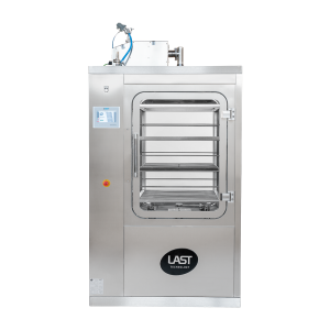
- The air recirculation and distribution system is installed in the upper part of the steriliser. The heating elements and cooling exchanger are arranged concentrically around the impeller of the recirculating air fan.
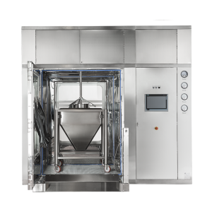
- The chamber is placed on a base that has been designed specifically to evenly distribute the weight on the floor.
- The loading cart-insertion and removal guides are placed on the bottom of the chamber; they are also height-adjustable.
- Two 1.5” tri-clamp ferrules are welded to the chamber for validation purposes (air particle sampling and temperature uniformity mapping).
- All of the chamber’s internal surfaces are mechanically polished and then undergo chemical degreasing, pickling and passivation treatments. Surface finish ≤ 0.35 micron.
- Floor-level chamber installation.
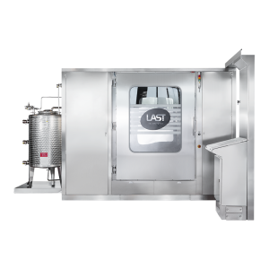
- Both doors (loading and unloading side) have been designed to be connected to the walls of the cleanrooms (“Bio-seal” interface).
Other machines belonging to this category
mail
Subscribe to our newsletter
Stay up to date with the latest news from LAST Technology